
A practical guide to understanding bale chamber pressure readings on round balers and large square balers — translating gauge numbers into bale density outcomes, recognising normal and abnormal pressure patterns, and using real-time pressure data to make in-field decisions that protect both bale quality and machine reliability
Most modern balers are fitted with some form of chamber pressure indication — a hydraulic pressure gauge on the baler frame, a bar-graph display on the tractor-mounted controller, or a numerical readout on a touch-screen density control panel. These instruments are there to help the operator make real-time decisions about forward speed, density settings, and machine condition. Yet a large proportion of baler operators admit to monitoring the pressure gauge only sporadically — checking it when something sounds wrong rather than reading it continuously as the primary quality-control instrument it is designed to be.
The pressure gauge is the baler’s most direct feedback mechanism. It tells the operator — in real time, while the bale is forming — whether the chamber is at the correct pressure for the target density, whether the crop conditions are changing as the baler moves through the field, whether the tractor is approaching its PTO limit, and whether something in the machine has changed that is preventing the chamber from reaching its set pressure. No amount of post-baling bale quality inspection provides as much actionable information as a pressure gauge read correctly during the baling pass.
This article covers how chamber pressure gauges work on both round balers and large square balers, how to interpret the readings during a normal baling cycle, what specific pressure patterns indicate about bale quality and machine condition, how to use the gauge to make in-field adjustments, and the relationship between chamber pressure readings and the PTO shaft load that the tractor and driveline must sustain.
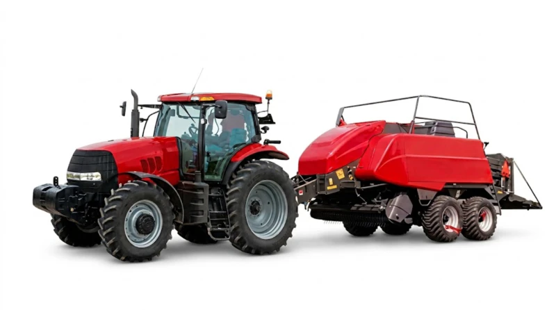
How Chamber Pressure Gauges Work: Round Baler vs Large Square Baler Displays
Chamber pressure indication systems differ between round balers and large square balers because the two machine types use fundamentally different mechanisms to create bale density — and therefore measure different physical quantities to represent the pressure applied to the forming bale.
Round Baler: Hydraulic Belt Tension Gauge
On a variable-chamber round baler, the chamber pressure is created by the hydraulic pressure in the belt tension cylinders that push the tension arms against the growing bale. The pressure gauge on a round baler reads the hydraulic pressure in this circuit — typically in bar or PSI — which is directly proportional to the force the belts are exerting on the bale surface.
The gauge typically sits at a fixed minimum reading during the early phase of bale formation (when the chamber is small and the belt tension cylinders are at their minimum extension), then rises progressively as the bale grows and the cylinder rods extend against the set accumulator pre-charge pressure. The final pressure — reached when the bale is full-size and the chamber is at maximum extension — is the density set point that the operator has established via the hydraulic pressure relief valve or electronic proportional valve.
Most round baler pressure gauges are graduated in bar (0–250 bar typical range) or PSI (0–3,600 PSI). The absolute pressure number is less important than its relationship to the operator-set target and to the baler manufacturer’s specified range for different crops.
Large Square Baler: Plunger Force or Friction Dog Pressure
Large square balers indicate density through one of two methods depending on age and specification. Older machines may display hydraulic pressure in the friction dog actuating circuit — the pressure that pushes the friction dogs (the bale channel resistance flaps) against the forming bale. Modern machines like the EP-9YFQ-2290XD with the NT03 system typically display a derived density value — calculated from the plunger load cell reading or the friction dog pressure — as a numerical density figure in kg/m³ or as a percentage of maximum density, updated at every compression stroke. The NT03 system displays both the current density reading and the target density set point simultaneously, allowing the operator to see at a glance whether the actual density is tracking the target.
Reading the Normal Pressure Cycle: What a Healthy Gauge Pattern Looks Like
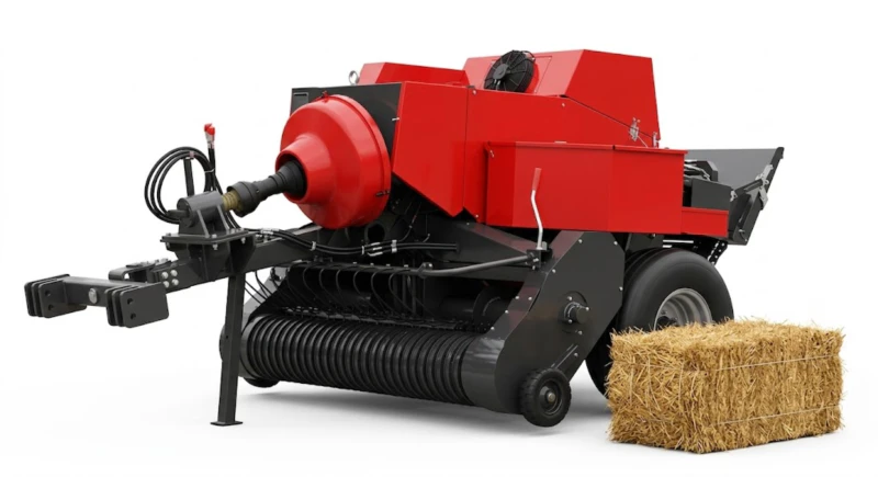
Round Baler: The Rising Pressure Profile
A normal round baler pressure cycle produces a characteristic rising profile when plotted against time: the gauge reads near-zero (minimum hydraulic system pressure) immediately after bale ejection as the new bale begins to form in the empty chamber; it then rises gradually over the bale formation period as the bale grows and the belt tension cylinders extend; and it reaches the set target pressure in the final 20–40 seconds before the bale-full signal triggers wrapping and ejection.
In a well-matched tractor and baler combination at the correct forward speed for the crop conditions, the pressure profile should look like a smooth ramp from minimum to target, with the target pressure reached consistently at approximately the same time in every bale cycle. Bale-to-bale variation in the time to reach target pressure indicates variation in swath density — more crop per metre of windrow fills the chamber faster and reaches target pressure sooner; less crop per metre takes longer.
The key normal-cycle indicators to monitor:
- Target pressure consistently reached: If the gauge reaches the set target on every bale, the density setting is achievable for the current crop and tractor combination. If the gauge reaches target on some bales but not others, swath density is inconsistent — thin sections are not filling the chamber fully before the bale length trip activates.
- Smooth rise without sudden spikes: A smooth pressure rise indicates uniform crop entry. Sudden spike-and-drop events during the bale build phase indicate slug entries — sections of windrow where more crop than normal entered the pickup simultaneously, temporarily overloading the chamber.
- Pressure holds at target: When the gauge reaches the set target, it should hold at that pressure (within ±5–10 bar) during the wrapping cycle before the bale is ejected. A pressure that drops rapidly from the target immediately after the bale-full signal indicates the belt tension system is not maintaining force during the wrapping phase — the bale is expanding slightly while being wrapped, reducing the final density.
Abnormal Pressure Patterns: What the Gauge Tells You When Something Is Wrong
Every departure from the normal pressure cycle pattern carries diagnostic information. The following abnormal patterns and their most likely causes provide a systematic starting point for in-field problem diagnosis.
Pattern: Gauge never reaches target pressure
The pressure builds but plateaus below the set target on every bale, or rises very slowly and the bale length trip activates before the target is reached.
Most likely causes: Crop density too low for the forward speed (increase speed or merge windrows); pressure setting too high for available tractor PTO power (reduce pressure target); hydraulic system fault limiting maximum pressure (check relief valve setting and system pressure).
Pattern: Pressure exceeds target and causes PTO overload
The gauge exceeds the set target and the tractor engine speed droops or the PTO slip clutch engages, indicating the chamber pressure is demanding more torque than the tractor can supply.
Most likely causes: Pressure set too high for the tractor’s PTO capacity at this crop density; crop density heavier than the setting was calibrated for (denser swath, higher moisture); hydraulic relief valve set above specification.
Pattern: Large sudden pressure spikes then rapid drop
During mid-bale formation the gauge suddenly spikes 30–60% above normal then returns to the baseline curve, occurring once or twice per bale cycle.
Most likely causes: Slug feeding from an uneven windrow — a dense clump of crop entering the pickup simultaneously. Reduce forward speed through uneven windrow sections; consider raking windrows more evenly before baling.
Pattern: Pressure fluctuates widely with no clear rise
The gauge reads erratically throughout the bale formation cycle, with no clear rising trend toward the target pressure.
Most likely causes: Belt slip on tension rollers (belts failing to maintain pressure against the bale); hydraulic system contamination causing erratic pressure control; accumulator pre-charge pressure incorrect (check nitrogen pre-charge against specification).
Pattern: Pressure rises faster than usual on every bale
The target pressure is reached significantly earlier in the bale cycle than normal, producing smaller or lighter bales at the same forward speed and density setting.
Most likely causes: Crop is denser or wetter than previous baling session (higher moisture = higher wet density = faster pressure rise); bale length trip is activating early (check trip adjustment); pickup is delivering more crop per rotation than expected from the windrow.
Pattern: Pressure drops at end of cycle before ejection
The gauge reaches target pressure, then drops 10–30 bar during the wrapping or tying cycle before bale ejection.
Most likely causes: Normal bale spring-back as chamber begins to open for ejection; hydraulic system leak allowing pressure bleed during the static wrapping phase; accumulator capacity insufficient for the hold duration required by the wrapping cycle.
Chamber Pressure and PTO Shaft Load: Reading Both Instruments Together
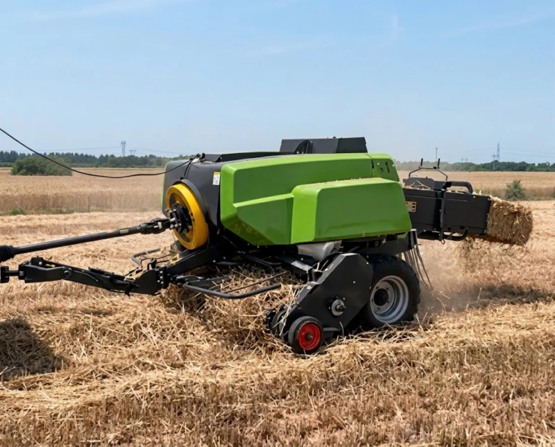
The baler’s chamber pressure gauge and the tractor’s engine speed indicator (or PTO load monitor on modern tractors) are a paired instrument set. Neither tells the complete story alone — the chamber pressure shows what the bale is demanding from the machine, and the tractor’s response shows whether the machine can deliver it sustainably.
The Four Operating Zones
Zone 1: Comfortable (Green)
Chamber pressure at or below target; tractor engine speed steady at rated rpm; no PTO overload signal. This is the correct operating zone — the baler is producing the target density without taxing the tractor. Maintain forward speed and settings.
Zone 2: Approaching Limit (Yellow)
Chamber pressure at target; tractor engine speed drooping 50–100 rpm below rated; no slip clutch engagement yet. The system is near its sustainable limit. Maintain current settings but do not increase forward speed or density. The next dense swath section may push into Zone 3.
Zone 3: Overload (Orange)
Chamber pressure above target; engine speed drooping more than 100 rpm; occasional PTO slip clutch engagement. The baler is demanding more than the tractor can sustainably supply. Reduce forward speed immediately. If Zone 3 persists at reduced speed, reduce the density setting.
Zone 4: Protection (Red)
PTO slip clutch engaging repeatedly; engine stalling or near-stalling. Stop forward movement immediately. Either a blockage has occurred (clear the pickup) or the density setting fundamentally exceeds the tractor-crop combination’s capacity. Reduce density setting before continuing.
The target operating condition is Zone 1 in normal swath sections with the buffer of Zone 2 available for denser swath sections without entering Zone 3. A system that operates in Zone 2 continuously has no reserve for normal field variation and will enter Zone 3 every time it encounters a section slightly denser than average. Plan the density setting so that Zone 2 is the upper limit of normal operation, not the steady-state condition.
Using Pressure Data for In-Field Decisions: A Quick-Reference Decision Table
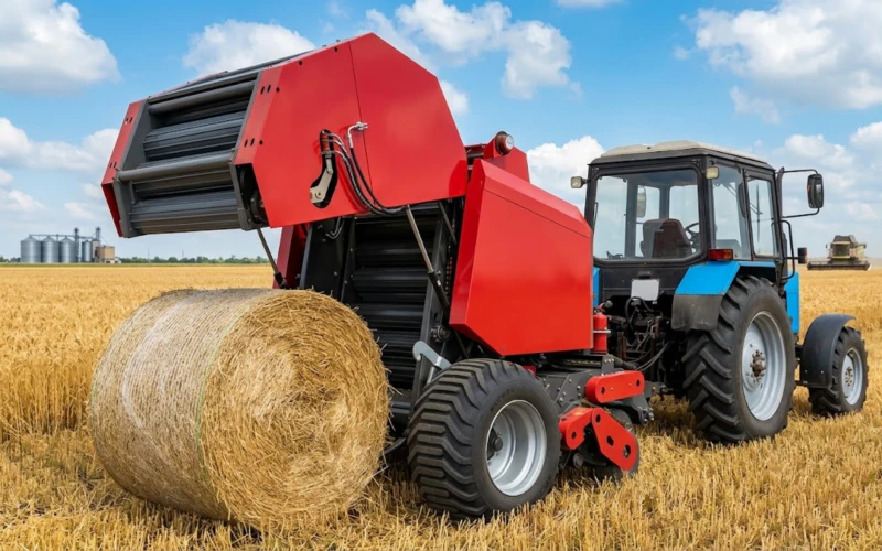
The following table translates pressure gauge readings into specific operator actions. Use it during the baling session as a decision support reference.
| Gauge Reading | Tractor Response | Interpretation | Action |
|---|---|---|---|
| At target, smooth rise | Engine steady | Correct operating condition | Continue; no change |
| Below target, never reaches | Engine light or steady | Crop too thin or speed too low | Increase forward speed; merge windrows; or accept lower density |
| Reaches target early, bales small | Engine steady | Crop denser or wetter than setting calibrated for | Reduce forward speed to extend bale fill time; or reduce density setting |
| Target reached; engine drooping | 50–100 rpm droop | Approaching tractor PTO limit | Reduce forward speed 10–15%; monitor; do not increase density |
| Above target; clutch slipping | >100 rpm droop or stall | System overload or blockage | Stop; clear blockage if present; reduce density setting |
| Sudden spike then drop mid-bale | Brief droop | Slug entry (dense windrow section) | Reduce forward speed in that windrow section; rake more evenly |
| Erratic, no clear rise pattern | Variable | Belt slip or hydraulic fault | Stop; inspect belts and hydraulic system; check accumulator pre-charge |
| Drops after reaching target | Steady during wrap | Normal spring-back; or hydraulic leak | If >20 bar drop, inspect hydraulic circuit for internal leak |
Часті запитання
My baler has a bar-graph display rather than a numeric gauge. How do I use it the same way?
Bar-graph density displays work on exactly the same principle as analogue gauges — they show the current chamber pressure or density as a proportion of the system’s maximum, typically divided into 5–10 segments with a marked target zone. The target zone is usually indicated by a different colour segment or a pair of arrows on the bar graph scale. Treat the bar graph identically to a numeric gauge: during normal baling, the bar should rise progressively from empty (bottom) to target (marked zone) and hold there during wrapping. All the same abnormal patterns apply — consistently not reaching the marked zone means below-target density; reaching the zone early on every bale means denser or wetter crop than the setting was calibrated for; erratic bar movement means belt slip or hydraulic instability. The only practical difference from a numeric gauge is that bar graphs do not allow precise pressure comparison between sessions — take a note of which segment the gauge normally reaches in a reference baling session and use that as your baseline for subsequent sessions.
What is the correct pressure setting for my round baler and how do I find it?
The baler operator manual specifies the hydraulic pressure range for each crop type — typically giving a minimum pressure for light crops and a maximum pressure for dense crops, with recommended starting points for the most common materials. Start at the manufacturer’s recommended starting pressure for your crop, produce five bales, and assess them by weight (if a scale is available) and by hand firmness. If the bales are lighter than the target or feel soft, increase pressure in 10–15 bar increments and produce another five bales. If the bales are at target density but the tractor engine is drooping under load, the pressure is too high for the tractor-crop combination — reduce pressure or forward speed. Record the validated pressure setting for each crop type in a field notebook and use it as the starting point for subsequent sessions of the same crop. A setting that produces correct density on a cool, dry morning may need slight reduction on a hot afternoon when the crop is drier and more compressible — check the first bale of each new session rather than assuming yesterday’s setting is still optimal.
Can I use the chamber pressure gauge to detect a PTO shaft problem before it causes a field failure?
Yes — certain developing PTO shaft problems produce characteristic pressure gauge signatures that can be detected before the failure occurs. A worn slip clutch that is slipping at below-normal torque shows up as a pressure gauge that repeatedly fails to reach the target, even in crop conditions and at forward speeds where target pressure was previously achieved — the slip clutch is absorbing energy that should be reaching the bale chamber. A PTO shaft universal joint with significant wear produces a cyclic vibration at the shaft’s rotation frequency that appears as a rapid oscillation superimposed on the normal pressure trace — visible on a sensitive gauge or electronic display even before the joint makes any audible noise. If the pressure gauge shows either of these patterns and there is no obvious change in crop conditions or settings to explain them, inspect the PTO shaft and slip clutch before the next baling session rather than continuing to operate.
How does the NT03 electronic density control on the EP-9YFQ-2290XD change how I read and respond to pressure data?
The NT03 system changes the operator’s role from active pressure manager to exception monitor. In automatic density control mode, the system continuously compares the measured plunger load against the target density and adjusts the friction dog pressure automatically — the operator sets the target once and the system maintains it across variable crop conditions without further input. What the operator monitors on the NT03 display shifts from “is the pressure reaching the target?” (the system handles this) to “is the system staying within the tractor’s PTO capacity?” and “are there exception events that the automatic system is flagging?” The NT03 display shows a PTO load indicator alongside the density readout — monitor this to ensure the automatic density adjustment is not driving the density control into territory that exceeds the tractor’s sustainable output. If the PTO load indicator is consistently at maximum while the density display shows the target is being met, the target density is too high for the tractor-crop combination and must be reduced manually despite the automatic system’s ability to achieve it momentarily.
Conclusion: The Pressure Gauge Is the Baler’s Most Useful Instrument — If You Read It
The chamber pressure gauge — whether analogue hydraulic, bar-graph display, or touch-screen density readout — is the baler’s real-time quality control instrument. It tells the operator more about what is happening inside the bale chamber than any post-baling inspection can reveal, because it provides information during bale formation when adjustments are still possible, not after the bale has been ejected and the opportunity for correction has passed.
Operators who read the pressure gauge continuously — treating it as the primary instrument that drives forward speed, density setting, and diagnostic decisions — produce more consistent bales, encounter fewer mechanical problems, and make better use of their tractor’s available PTO capacity than operators who set the density once at the start of the day and rely on bale feel at the end. The instrument is already fitted to the machine. Using it fully is simply a matter of knowing what the numbers mean and responding to them as the primary guide to everything the baling system is doing.
Balers with Precision Density Monitoring — Factory Direct from Balershay
We supply round balers and large square balers with hydraulic pressure gauges, electronic bar-graph density displays, and touch-screen density control systems including the NT03 on the EP-9YFQ-2290XD. Visit balershay.com to explore our full baler range, or contact our team for guidance on density monitoring specifications for your target crop and operation.